Sin categoría

What is a stepper motor ?

What is a stepper motor ?

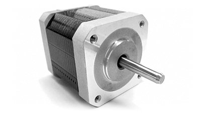
A stepper motor is one that rotates in an intermittent manner, moving by a fixed angle at each step rather than continuously rotating its shaft.

The movement of the second hand on a clock, for example, which advances one second at a time, could be achieved by using a stepper motor that moves in 6°increments, once every second.

So, how does a stepper motor achieve this characteristic of rotating its shaft by a fixed angle at each step?

The secret lies in the use of electrical pulses. A pulse is an electrical signal produced by turning a power supply on and off, with each such switching counting as one pulse. A stepper motor uses these pulses to achieve precise mechanical control over the angle and speed of rotation.

Stepper motors can be broadly grouped into the following three categories depending on the structure of their rotor.

Permanent magnet (PM) motor:

    The rotor contains a permanent magnet. A disadvantage of this structure is that it can not provide flexibility over the angle of rotation (step angle).

Variable reluctance (VR) motor:

    The rotor contains cores structured like the teeth of a gear. This allows for more flexibility in setting the step angle.

Hybrid (HB) motor:

    The rotor contains both permanent magnets and cores structured like the teeth of a gear. This type of motor is used in a wide variety of applications, combining the advantages of PM and VR motors.

Operation principle of HB stepper motors:

The rotor is designed with a cylindrical permanent magnet positioned between two cores, these being concentric to the motor shaft and offset by a half pitch from each other. The rotor rotates by a fixed step angle each time a pulse is input.

Stepper motors can also be grouped into the following two categories based on electric current flow in the coil:

Unipolar motor:

Current in a unipolar motor always flow through the coil windings in the same direction. While this keeps the associated control circuit simple, it produces less torque than a bipolar motor.

Bipolar motor:

Current in a bipolar motor can flow through the coil windings in either direction. While this requires a more complex control circuit than a unipolar motor, it produces more torque.

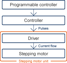
What is a stepper motor driver?

Stepper motors are used in conjunction with a driver circuit. The driver controls the angle and speed of motor rotation based on the input of electrical pulses from the controller.

Features of stepper motors:

Stepper motors differ from other motor types in the following ways.

Advantages:

  • As the angle of rotation is determined by the number of pulses (digital input), control of position (angle of rotation) is simple
  • Can rotate at low speeds
  • Can use open-loop (non-feedback) position control
  • Excellent ability to remain locked in position when halted

Disadvantages:

  • Requires a drive circuit
  • Loss of synchronization can occur due to factors such as unexpected changes in load
  • High level of vibration and noise

Applications for stepper motors:

The excellent halting accuracy, high torque at medium and low speeds, and superior responsiveness of stepper motors means that they can be used in a wide range of drive applications that demand precise control.

  • Production machinery
  • Medical equipment
  • Laboratory analytical instruments
  • ATMs
  • Vending machines
  • Ticket vending machines
  • Copiers
  • Robots
  • Optical disk drives (Blu-ray and DVD drives, etc.)
  • Laser printers
  • Digital cameras
  • Air conditioning louvers
  • Amusement machines

Santiago Martinez – www.windydaysproducts.com

ATV Tire Size Explained: A Comprehensive Guide.

ATV Tire Size Explained: A Comprehensive Guide

Your quad is a do-anything machine. ATV’s are great for getting things done and for recreation too. But now you’re looking at your tires. Maybe you’ve blown one or they’re getting bald. Or maybe you just want a more aggressive tread pattern and a bigger tire. The problem is you’re a little lost when it comes to your ATV tire size.

How big can you go? Should you go big? How do you even know what all these numbers represent?

Don’t worry, we’ve got you covered. We’ll answer all those answers and more in this comprehensive guide.

How Do You Read ATV Tire Sizes?

So, you’re shopping around for tires and you see one listed with a size like 26×10-12. Or, worse yet, you find something listed like 206/80R12.

What the heck does all that mean?

First, you need to figure out if you’re dealing with standard or metric ATV tire sizes.

ATV Tire Size Explained: ATV Tire Sizes: Standard Tire Sizing Chart

Standard format is much more common on ATV tires than metric. You might see a tire size written 26×10-12 or, occasionally, 26x10x12. This format is pretty straightforward. It uses three numbers to sum up the size:

    Tire diameter in inches

    Tire width in inches

    Wheel diameter in inches

ATV Tire Size Explained: ATV Tire Sizes: Metric Tire Sizing Chart

If you see a tire size that looks like this: 205/80R12, you know you’re dealing with metric. The metric format is exceedingly rare for ATVs and odds are you’ll never come across it. But if you do, the letter thrown in the middle of those numbers is a dead giveaway. In metric, you always have three numbers and a letter:

    Tire width in millimeters

    The aspect ratio as a percent

    A letter for construction type (usually “R” for “radial”)

    Wheel diameter in inches

There may be other numbers and letters before and after these, but they’re not important for understanding your ATV tire size.

Breaking Down ATV Tire Sizes by the Numbers

Knowing how to read those tire sizes is just the first step. You really need to know how to use them. Is 26 inches a reasonable diameter for your quad? What kind of width do you need?

Tire Diameter Breakdown

When you’re considering replacing all of your tires, you’ll want to make sure you get something that will actually fit on your stock vehicle.

Your typical ATV tire diameter fits within a range of about 20 inches for the smallest machines to about 30 inches for your more factory mud-equipped machines.

Basically, your quad will typically fit into one of few categories:

    Sport quads—20 to 25 inches

    Utility quads—24 to 28 inches

    Factory mud or rock equipped quads—27 to 30 inches

Keep in mind that you’ll want to keep within a couple inches of your stock tire size. If you go too big, you’ll start to rub on your fenders (among other issues). If you go small—well, that’s just silly.

Tire Width Breakdown

Tire width is easier to understand. Choosing the right tire width has a lot to do with your own preferences and riding style.

A wider tire tends to give you a flatter tread pattern and more grip. A narrow tire gives you a little more control.

ATV’s usually have a wider tire on the rear than on the front to get the best of both tires. A typical rear tire on a quad will be 10 to 11 inches wide while a front tire will be 7 to 8 inches wide.

But matching your tire width to your riding style isn’t the only thing you need to consider. You also need to make sure it’ll physically fit on your chosen wheel. There are two main ways to make sure it’ll fit.

    Check the tire manufactures wheel recommendation. They should provide a range of wheel widths that the tire is designed to work with.

    If you can’t find that info, the general rule of thumb is to go with a wheel that’s about two inches narrower than your tire’s width. This is a general guideline and not guaranteed to work for every tire, but our experience shows that it’s right most of the time.

Wheel Diameter Breakdown

This one is non-negotiable. You have to make sure your tire’s wheel diameter matches your actual wheel diameter.

Most off-road wheels tend to be 10 to 12 inches in diameter—which is convenient considering most off-road tires are designed to fit those wheels. That’s a good size as it gives your tire plenty of cushion between the tread and rim, which results in smoother rides and more protection for your rims.

Of course, you can end up with bigger wheels if you have bigger tires, but we’re getting ahead of ourselves.

Choosing the Right Size Tires for Your ATV

You don’t need any old tire. You have to choose the perfect ATV tire size for you. After all, you ride your own way and have your own needs.

We’re going to simplify ride style to three main types:

    Work/chores

    Trail/dune riding

    Rocks/mud riding

For a workhorse ATV, it’s not a bad idea to stick with stock. It’ll give you the expected traction and power you need.

Trails and dunes demand high traction, and you get that by going wider. You don’t necessarily need a taller tire, but a wider one will give you the grip you need.

Dominating rock gardens and taking on bounty holes is done best with a big tire. But going big isn’t as simple as just buying the biggest tire you see.

Can I Put Bigger Tires on My ATV?

The short answer is yes.

Here comes the long answer.

Every ATV has a theoretical maximum tire size it can fit without modifying the suspension. It’s typically about one to two inches bigger than your stock tires. So if your ATV came with a 27-inch tire, you could probably fit a 29-inch tire without too much trouble.

But what if you want to go bigger?

That takes some work. You’ll either need to invest in a lift kit or some offset A-arms. These types of kits will often tell you what the max tire size is when you have them installed.

You can’t go big without some consequences though. Namely, you’ll lose torque due to the increased diameter (big tires like a high-gear kit!) and the extra weight. The weight can also put extra strain on your clutch and shorten the life of your clutch belt.

Luckily, you can get your torque back with a transmission gear reduction.

You can also bolster your clutch with heavy-duty drive belts and eek out even more torque with a clutch kit.

So now that you’re equipped with knowledge, go equip yourself with some tires. Get the ATV tire size you want, and ride with confidence.

By Kavan Wright, www.superatv.com

Elasticity of Materials – Basic Principles.

Elasticity of Materials – Basic Principles:

In the science of physics, elasticity is the ability of a deformable body (e.g., steel, aluminum, wood, etc.) to resist a distorting effect and to return to its original size and shape when that influence or force is removed. Solid bodies will deform when satisfying forces are applied to them.

The elasticity concept of solid materials is the deformation with the external force application and recovery to its original shape after the forces removed. Parameters are: stress (force per area) and strain (deformation per unit length).

Elasticity of Materials – Basic Principles: Young’s Modulus Explained

Young’s Modulus/Initial Modulus is the initial part of a stress/strain curve and describes the ability to resist elastic deformation under load. It describes a material’s propensity to retain its shape, even when it is being stretched, pulled, twisted, or compressed.

So, Young’s Modulus=Stress/Strain.

When a material has a high modulus, even under extreme strain the material resists the initial force and recovers well. For a lower modulus material, strain stresses it and creates the risk of breaking, which is illustrated in the stress-strain curve below.

Terms Related to Young’s Modulus:

Stress: A tension created by the application of a lengthwise load.

Strain: Change in length from stress acting parallel to the longitudinal axis of the material.

Creep: This is time-related, non-recoverable damage due to sustained stress.

Fatigue: Fatigue is when a material weakens due to repeatedly applied loads.

Stiffness: A stiff material has a high Young’s Modulus.

Deformation: Also known as plastic deformation, this is the warping that occurs under stress.

Elastic limit: This is the limit beyond which the material is deformed.

Yielding: Just beyond the elastic limit is permanent deformation known as yielding.

Strain Hardening: Beyond yielding, this is a maximum or ultimate stress.

Fracture: Beyond ultimate stress is the fracture, or breaking, point.

Elasticity of Materials – Basic Principles: High Modulus Materials

A high modulus is preferable in a wide variety of industrial and commercial materials for purposes of resilience, safety, and reliability.  Because of the more desirable tensile characteristics for specific applications, high modulus material variants are often more expensive than standard modulus materials.

References:

    1. Todhunter I. A history of the theory of elasticity and of strength of the materials from Galilei to the present time, Vol. II. Saint-Venant to Lord Kelvin. King’s College, Cambridge: Pearson; 1893.

    2. Timoshenko SP, Goodier JN. Theory of Elasticity. 3rd ed. New York: McGraw-Hill; 1970.

Santiago Martinez – www.windydaysproducts.com

Types of transmissions.

Mechanical, hydraulic, electrical transmissions.

It is not very long ago that engineers had no alternative but to use mechanical drives in every situation, and there is thus a strong tendency to continue thinking only in terms of power transmission by mechanical connection; but at the present day, four possible methods of transmission are available to a machinery designer. These are the mechanical system, the hydraulic system, the pneumatic system and the electrical system. In considering the relative merits of these alternatives, the major and overriding point is that any one of the last three gives complete freedom for the functional design of a machine; this is because the transmission consists essentially of a flexible arrangement of pipe or cable between the driving and the driven members In the case of a mechanical system, however, the configuration of the machine must be such as to permit positive connection between driving and driven components. In other words, the flexibility of the hydraulic, pneumatic and electrical system allows the functional requirements of the machine to be the foremost consideration, whereas the rigidity of a mechanical system imposes severe limitations and forces a designer to think predominantly in terms of a suitable mechanical route. The second major point is that each of these three flexible systems can provide step-less speed variation over a wide range and can be stalled without damage; the latter feature is an advantage over variable-speed V-belt drives and so is the wider range of step-less variation which can be affected. On the other hand, a positive mechanical connection between components is most suitable where a precise fixed speed is required under variable load.

The efficiency of a mechanical system decreases directly with the number of components, since the losses are cumulative in a sequence of shafts, bearings, joints and gears, chains or belts. Thus, when power has to be transmitted through a complex mechanical arrangement in order to reach a certain component, the efficiency can be quite low (and the cost high). But the efficiency of an hydraulic, pneumatic or electrical drive is not affected by the relative positions of the driven member and the power source. Consider, for example, the transmission from a tractor engine to the auger of a baler: in one current design selected at random, the drive is through six pairs of gears and one V-belt, with considerable lengths of shafting, four universal joints and appropriate bearings; the efficiency will be about 75%.

Comparisons between mechanical drives and the alternative types of drive need to be made on a specific basis, because the complexity of the mechanical system is a very pertinent factor. It is false to make a general assumption that a mechanical drive is always more efficient and less costly: this is only true in the case of the more simple mechanical arrangements. The point also applies when the extent or complexity of the mechanical system is due to a large speed ratio requirement, rather than to the position of the driven member on the machine; even when a mechanical system has a higher efficiency than the equivalent non- mechanical system, the latter may actually be justified on the grounds of a number of secondary advantages —such as complete safety, low maintenance under adverse conditions, no limitations on angles of movement, and compactness etc.—or because of the freedom of design which is afforded, or the ease and range of step-less speed variation which can be effected.

Pneumatic methods of transmission are most suitable for low power and high speeds, and are of particular value where a reciprocating action is required.

Hydraulic versus electrical systems:

Essentially, both hydraulic and electrical transmission systems are very similar. The hydraulic system consists of a pump driven by an engine, or other source ot power, and supplying fluid at a known velocity and pressure through piping to an hydraulic motor; the electrical system consists of a generator driven by an engine and feeding through wiring to an electric motor elsewhere. In both cases, it is possible to effect step-less speed control, the motors have excellent torque-speed characteristics for variable-load installations, and the system can be stalled without damage to the transmission or overload on the engine. In the case of power transmission between a tractor and a machine or between the engine and components of a self-propelled machine, there is little doubt that an hydraulic system is preferable to an electrical system. The latter is difficult to complete!) seal, is not so immune from damage, is not safe and generally does not have as high an efficiency. There is also the obvious advantage in that an hydraulic system can also be utilized to operate linear jacks for position control of individual parts of a machine. Hydraulic systems are not only trouble-free as long as the oil is kept clean, but they are also foolproof; this is not always true with an electrical system. Another advantage of the hydraulic over the electrical method is in the ease of effecting speed variation. In both cases, the speed of a motor can be varied by changing the speed of the engine and therefore of the pump or generator; this method is commonly used in the case of electrical transmission but has the disadvantage that the engine cannot be run at its optimum speed. With an hydraulic system, a variable-delivery pump can be used and the engine operated at constant speed; the equivalent electrical arrangements are less simple.

To permit variation of the speed of any one of a number of motors in the same system, it is necessary to insert a flow control valve in the line to each hydraulic motor, or a rheostat in the comparable electrical circuits. Although the latter may be less costly, the hydraulic arrangements for speed control are in general more suitable agricultural usage; further more, electrical systems usually require special arrangements for starting under load and must be specifically designed to withstand stall conditions.

Mechanical hydraulic electrical transmissions: This table compares general advantages associated with mechanical, pneumatic, hydraulic, and electrical means of producing linear mechanical motion.

CharacteristicsMechanicalPneumaticHydraulicElectric
Complexityvery simplesimplemediumhigh
Peak powerhighmediumvery highhigh
Sizemediumlowlowmedium
ControlgearboxvalvesvalvesElectronic controller
Accuracygoodlowhighgood
Speedmediumfastlowfast
Purchase costlowlowhighhigh
Maintenance costlowlowhighlow
Total costlowlowhighmedium

Santiago Martinez – www.windydaysproducts.com

Mechanical hydraulic electrical transmissions chart

3D CAD applications.

3D CAD applications short description:

Autodesk Inventor is a computer-aided design application for 3D mechanical design, simulation, visualization, and documentation developed by Autodesk. It was released in 1999.
It allows 2D and 3D data integration in a single environment, creating a virtual representation of the final product that enables users to validate the form, fit, and function of the product before it is ever built. Autodesk Inventor includes parametric, direct edit and freeform modeling tools as well as multi-CAD translation capabilities and in their standard DWG drawings.

SolidWorks is a solid modeling computer-aided design (CAD) and computer-aided engineering (CAE) application published by Dassault Systèmes. Released in 1995.
It is a solid modeler, and utilizes a parametric feature-based approach which was initially developed by PTC (Creo/Pro-Engineer) to create models and assemblies. Parameters refer to constraints whose values determine the shape or geometry of the model or assembly. Parameters can be either numeric parameters, such as line lengths or circle diameters, or geometric parameters, such as tangent, parallel, concentric, horizontal or vertical, etc. Numeric parameters can be associated with each other through the use of relations, which allows them to capture design intent.

AutoCAD is a commercial computer-aided design (CAD) and drafting software application. Developed and marketed by Autodesk, AutoCAD was first released in December 1982 as a desktop app running on microcomputers with internal graphics controllers. Before AutoCAD was introduced, most commercial CAD programs ran on mainframe computers or minicomputers, with each CAD operator (user) working at a separate graphics terminal.
AutoCAD is used in industry, by architects, project managers, engineers, graphic designers, city planners and other professionals. It was supported by 750 training centers worldwide in 1994. It was released in 1979.

Wich is better ?

Solidworks against Inventor, seemed like a challenge, they push one another to become better. As far as I’m concerned, it is suitable for this competition to continue for years to come. These two are fantastic competitors.

Because they’re similar programs, SolidWorks and Inventor are both great options for 3D modeling software. Both are industry standards for a number of reasons, and both offer a wide range of simulations to thoroughly test designs before they come to life.

Inventor Advantages

Although it’s often overshadowed by its more famous sibling AutoCAD, Inventor actually fills a lot of gaps in Autodesk’s usage roster. Here’s a look at some of its best features.

Direct-edit and free-form modeling tools: As an alternative to parametric design’s prediction-based process, Inventor offers to direct-edit and free-form modeling.
Automation of advanced geometries: Another function automates the math behind scenes for complex moving parts, like kinetic blades or support wires. This allows one to focus on the big picture of a design without getting bogged down by small details.
Quick loading time: Inventor distinguishes itself by loading the graphic parts of a design separately from the material and geometric data. This makes it noticeably fast since the latter are by far the largest data hogs of most designs.
Free education license: Students benefit from a free three-year subscription to all Autodesk products, including Inventor. This can save individuals thousands of dollars during their studies and let them become very familiar with the program before deciding if they’ll need it in their professional lives.
Simulation tools: Inventor has its own ways to test 3D designs in real-world situations. Its Dynamic Simulation module, in particular, applies specific types of pressure to key points, like torque to joints. A favorite among many is the burst weldment tool. This lets one undo a weld to simulate what would happen if it gave way in an emergency situation.

Inventor Disadvantages

Inventor closes the gap with SolidWorks with each new update, but it’s still not for everybody.

Steep learning curve: Generally speaking, Autodesk products aren’t known for their user-friendliness, and unfortunately, Inventor is no exception. There isn’t a huge online community, either, although Autodesk offers tutorials and support documents on its official page.
Support priority: While Autodesk does provide support through many avenues, those who have purchased more expensive licenses receive priority in the support queue.

SolidWorks Advantages

SolidWorks established 3D modeling standards for engineering CAD, but it hasn’t depended on its pedigree to do the heavy lifting. Throughout years of operation, SolidWorks has added a host of other features that complement and expand on CAD needs.

Simulation tools: One could say that SolidWorks’ options for testing designs have lapped the current needs. They give you high-repetition stress tests, temperature and object pressure measures, and a host of other real-world standards that one can mix and match to see exactly how a design will perform before buying a single beam or screw. This saves not only money but also building time and material waste – valuable factors in the manufacturing process.
Sustainability tool: Speaking of helping the environment, SolidWorks also has a sustainability tool that determines the environmental impact a design will have. It’s an eye-opening feature that matters more than ever as industry is put under more and more pressure to create products effectively and responsibly.
AR/VR: SolidWorks is one of the first companies to recognize the benefits of augmented and virtual reality in practical design. This tool from their 2018 and 2019 updates can be used to inspect a design from every angle and test its usability in a variety of environments and situations beyond the standard math of simulations.
Large design review: With SolidWorks, there’s plenty of room to grow. The large design review offers the power to design, test, and model pieces with millions of components without burning out a computer’s CPU.
CAM design to manufacture: SolidWorks is a soup-to-nuts system, beginning with 2D sketching and 3D modeling and ending with simulations and preparing for the manufacturing process.

SolidWorks Disadvantages

SolidWorks strives to be the people’s solid modeling software, but sometimes that means sacrificing one strength for another. Here are some of SolidWorks’ weak points that may break the deal for you.

Not ideal for architecture: Despite the fact that SolidWorks has a respectable 2D sketching module, it’s made to accommodate transitioning to 3D modeling, and that’s reflected in its structure. There aren’t any tools, for example, that architects could use to keep up with building codes, proportions, and building design.
No free student license: Unlike Autodesk’s menagerie, SolidWorks doesn’t have a free educational use license (though they do have a reduced cost student license). Because of this, many students, teachers, and educational institutions have to pass on SolidWorks.

Conclusion (my thoughts)

If you are a newbie, start with SolidWorks, it is very easy to use.
if you have AutoCAD background, then use Inventor. it will be very intuitive for you.
Both are AWESOME CAD applications.

Santiago Martinez

Industrial  Engineer

www.windydaysproducts.com

Welding Process.

Welding Process.

What Is Welding?

It´s the process of fusing two parts or pieces together using heat and/or pressure to create a joint. This resulting joint may also be called a seam or weldment. To create the seam, welding uses intense heat to melt the filler metal and the original metal together while being protected by a shielding arc created by gas that’s specific to the type of welding machine used.

Types of Welders

To create the heat necessary to melt various compounds together to create a seam, a welding machine is necessary. The most common types of welders are stick, MIG/flux-cored and TIG. Although you may also find plasma arc, gas tungsten arc, atomic hydrogen and energy beam units, these are typically reserved for highly skilled professionals. The core models are more than sufficient for the novice welder.

Welding Process: Understanding Equipment Types

Take a look at these standard types of equipment and learn about different types of welding to see which would be the best welder for your projects.

Stick Welders (SMAW or Shielded Metal Arc Welding)

Economical and effective, stick welding is the most popular choice for home shops. It works both in the workshop and outside, produces strong welds, and works on most alloy metals — even dirty or rusty surfaces. Stick welders can pose a challenge, however. Finished welds must be cleaned.

MIG Welders (GMAW or Gas Metal Arc Welding)

MIG (metal inert gas) welding is an excellent choice for beginning welders. This easy-to-handle machine is usually spool-fed to create professional-looking joints on both thick and thin metals. MIG welding requires separate shielding gas but doesn’t require chipping and cleaning slag as the stick welding process can. This makes for a faster and easier welding experience.

Flux Arc Welders

A flux arc welder offers simple and efficient welding on steel, aluminum and stainless steel. Some flux-core wires shield the arc from contamination without the need for an additional shielding gas. This feature makes a flux-cored welder an excellent choice for outdoor use as it works effectively on dirty or rusty metals, creating a thick, reliable seam.

TIG Welders (GTAW or Gas Tungsten Arc Welding)

TIG (tungsten inert gas) welding is a bit more complex to learn but offers a level of precision that other welding machines can’t. TIG welders require shielding gas but offer greater control and the ability to fine-tune the current with the use of an amperage foot pedal. TIG welding is good for thin alloy steel, aluminum, magnesium and copper alloys.

Multi-Process Welders

If you want to take advantage of several different types of welding but lack the space to store multiple welding machines, a multi-process welder may be your best choice. Housing several different processes inside a single machine, this equipment combines multiple functions, like MIG/flux-cored, TIG and stick welding, in a single unit.

Welding Process: Buying Your First Welder

There’s no welder that’s perfect for every craftsperson. That’s why it’s important to understand your task, goals and budget.

Research your workload and determine the types of metal you’ll most often work with, as well as their thickness. For example, are you primarily working to fix cars? Create metal sculptures? Build backyard furniture? Or are you performing maintenance on heavy-duty farm equipment?

Don’t just stop with your first project. You may need to repair a metal fence this weekend, but try to also see what’s down the road. Have you wanted to add a spare-tire mount to your trailer and didn’t know where to start? This helps to give you an idea of the type of machine and amount of training you’ll need to be successful.

Maintaining a Healthy Respect for Your Welder

As with all power tools, safely using a welder requires a healthy respect for the welding equipment. The correct safety gear and equipment will protect you against many things, but be aware of the risk of electric shock, noise hazards, burns, exposure to UV (ultraviolet) and IR (infrared) radiation, as well as fumes and gases.

That’s why it’s essential to save part of your budget for the right welding safety and protective gear. Your welding machine documentation will tell you what you need. For example, look for:

  • A quality welding jacket
  • Light- and heavy-duty welding gloves
  • A welding hood or welding helmet with the appropriate lens for your machine
  • A welding cap
  • Several pairs of safety glasses
  • Steel – toe shoes 
  • Earplugs

Reliable fume extraction solutions should also be part of your safety gear shopping list and budget.

Learning a new skill can be both exciting and overwhelming. Remember to take your time, learn as much as possible about your equipment and practice your new craft often. You’re well on your way to adding a skill with a great payoff — whether you’re working at home or on the jobsite.

Caution: Follow the welding equipment manufacturer’s instructions for use and safety, including the use of welding safety equipment and other safety gear

Santiago Martinez – www.windydaysproducts.com